Resources

Readying Enterprise Networks for Artificial Intelligence

Using ExtraHop and LiveWireTogether for Efficient Network Security Identification and Investigation
Whitepapers
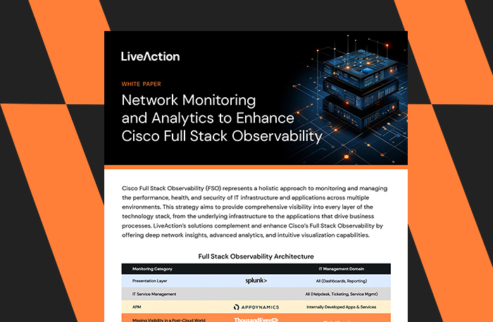
Network Monitoring and Analytics to Enhance Cisco Full Stack Observability
Whitepapers
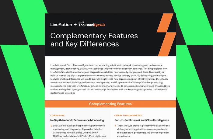
LiveAction & ThousandEyes: Complementary Features & Key Differences
Whitepapers

Infographic: Network Performance Monitoring Trends 2024
Whitepapers

Network Performance Monitoring Trends Report 2024
Whitepapers

Decoding the Truth: Network Packets Don’t Lie
Whitepapers
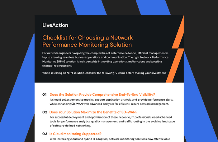
Checklist for Choosing a Network Performance Monitoring Solutions
Whitepapers

Network Performance Monitoring: 7 Reasons Why Good Enough Isn’t Good Enough
Whitepapers