
Signal Encoding, Fast Ethernet Environment – Signal Encoding
Fast Ethernet Environment – Signal Encoding
A number of ways are defined for representing a bit stream with an electrical signal. In the 10 Mbps Ethernet section of the Compendium there is a description of Manchester encoding. In 100 Mbps Ethernet there are several different encoding schemes that are available. The one that is used depends on the specific implementation being engineered. These are not interchangeable standards.
Encoding Standards in the Fast Ethernet Environment
- MLT-3 MultiLevel Transition
- NRZI Non-Return to Zero, Inverted
- T4 Multiplexing
- 4B/5B And 8B/6T Code Representations
4B/5B And 8B/6T Code Representations
Examples of 4B/45 and 8B/6T Data Encoding
4B5B Example
In order to send information using 4B5B encoding, the data byte to be sent is first broken into two nibbles. If the byte is 0E, the first nibble is 0 and the second nibble is E. Next each nibble is remapped according to the 4B5B table. Hex 0 is remapped to the 4B5B code 11110. Hex E is remapped to the 4B5B code 11100.
In 100BASE-FX and 100BASE-TX, the 4B5B replacement happens at the PCS sublayer of the Physical layer. Information is then further encoded for transmission using NRZI in 100BASE-FX at the PMA sublayer, and MLT-3 in 100BASE-TX at the PMD sublayer.
| 4B5B Encoding Table | ||
| Data (Hex) | (Binary) | 4B5B Code |
| 0 | 0000 | 11110 |
| 1 | 0001 | 01001 |
| 2 | 0010 | 10100 |
| … | … | … |
| D | 1101 | 11011 |
| E | 1110 | 11100 |
| F | 1111 | 11101 |
8B/6T Example
In order to send information using 8B6T encoding, the value of the data byte is compared to the values in the 8B6T table. Every possible byte has a unique 6T code, a set of 6 tri-state symbols. Unlike 4B5B, 8B6T completely prepares the data for transmission; no further encoding is required.
100BASE-T4 is currently the only technology which uses 8B6T encoding. It performs 8B6T encoding at the PCS sublayer of the Physical layer. 100BASE-T4 then demultiplexes the 6T codes onto three wire pairs.
| 8B6T Encoding Table | ||
| Data (Hex) | (Binary) | 8B6T Code |
| 00 | 0000 0000 | +-00+- |
| 01 | 0000 0001 | 0+-+-0 |
| …. | …. …. | …… |
| 0E | 0000 1110 | -+0-0+ |
| …. | …. …. | …… |
| FE | 1111 1110 | -+0+00 |
| FF | 1111 1111 | +0-+00 |
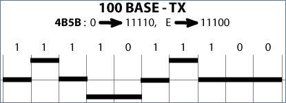
Multi-Level Transition (MLT-3) Encoding
MLT-3 encodes a bit as presence or lack of transition, exactly as in NRZI. What makes MLT-3 different is that the base waveform is a 3-state alternating wave. Rather than alternating between 0 and 1 as in Manchester encoding and NRZI, MLT-3 alternates from -1 to 0 to +1, back to 0, then back to -1, repeating indefinitely. A zero is encoded as a halt in the back-and-forth progression. It may be useful to think of MLT-3 as a stop-and-go sine wave, encoding 0 as stop and 1 as go. Using MLT-3, it is therefore possible to represent four or more bits with every complete waveform, at 0, +1, 0, and -1.
The data being transmitted in this example is the hexadecimal byte “0E”. First, the byte is broken down into four bit “nibbles”, giving a nibble of “0” and a nibble of “E”. Then, each nibble is looked up in a table to find the byte code associated with that hexadecimal number. The code for “0” hex is “11110” and the code for “E” hex is “11100”. Finally, the byte codes are transmitted onto the wire using MLT-3 encoding.
For a discussion of the reasoning behind the association of four byte “nibbles” with five byte codes, refer back to the DATA ENCODING SECTION of this Fast Ethernet section
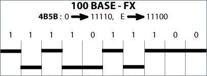
Here, we see an example of signal encoding in Non-Return-To-Zero, Invert-on-one. NRZI uses a half-wave to encode each bit. Rather than transition through ground at each bit like Manchester encoding, NRZI uses the presence or absence of a transition to signify a bit (indicating a logical 1 by inverting the state).
The data being transmitted in this example is the hexadecimal byte “0E”. First, the byte is broken down into four bit “nibbles”, giving a nibble of “0” and a nibble of “E”. Then, each nibble is looked up in a table to find the byte code associated with that hexadecimal number. The code for “0” hex is “11110” and the code for “E” hex is “11100”. Finally, the byte codes are transmitted onto the wire using NRZI encoding.
For a discussion of the reasoning behind the association of four byte “nibbles” with five byte codes, refer back to the DATA ENCODING SECTION of this Fast Ethernet section.
100BASE-T4 Multiplexing and Demultiplexing
In this image, we can see how data is transmitted by the Ethernet card and demultiplexed out onto three pairs of the Category 3 Cable. Bytes are multiplexed at the receiving end and placed back in the correct order. The fourth p air of the wire is used for collision detection. In this way, each wire only has to carry 33.3 Mbps, for an aggregate throughput of 100 Mbps. This is how 100 Mbps Ethernet can run on Category 3 unshielded twisted-pair cable.
4B/5B And 8B/6T Code Representations
Examples of 4B/45 and 8B/6T Data Encoding
4B5B Example
In order to send information using 4B5B encoding, the data byte to be sent is first broken into two nibbles. If the byte is 0E, the first nibble is 0 and the second nibble is E. Next each nibble is remapped according to the 4B5B table. Hex 0 is remapped to the 4B5B code 11110. Hex E is remapped to the 4B5B code 11100.
In 100BASE-FX and 100BASE-TX, the 4B5B replacement happens at the PCS sublayer of the Physical layer. Information is then further encoded for transmission using NRZI in 100BASE-FX at the PMA sublayer, and MLT-3 in 100BASE-TX at the PMD sublayer.
| 4B5B Encoding Table | ||
| Data (Hex) | (Binary) | 4B5B Code |
| 0 | 0000 | 11110 |
| 1 | 0001 | 01001 |
| 2 | 0010 | 10100 |
| … | … | … |
| D | 1101 | 11011 |
| E | 1110 | 11100 |
| F | 1111 | 11101 |
8B/6T Example
In order to send information using 8B6T encoding, the value of the data byte is compared to the values in the 8B6T table. Every possible byte has a unique 6T code, a set of 6 tri-state symbols. Unlike 4B5B, 8B6T completely prepares the data for transmission; no further encoding is required.
100BASE-T4 is currently the only technology which uses 8B6T encoding. It performs 8B6T encoding at the PCS sublayer of the Physical layer. 100BASE-T4 then demultiplexes the 6T codes onto three wire pairs.
| 8B6T Encoding Table | ||
| Data (Hex) | (Binary) | 8B6T Code |
| 00 | 0000 0000 | +-00+- |
| 01 | 0000 0001 | 0+-+-0 |
| …. | …. …. | …… |
| 0E | 0000 1110 | -+0-0+ |
| …. | …. …. | …… |
| FE | 1111 1110 | -+0+00 |
| FF | 1111 1111 | +0-+00 |
MLT-3 MultiLevel Transition
Multi-Level Transition (MLT-3) Encoding
MLT-3 encodes a bit as presence or lack of transition, exactly as in NRZI. What makes MLT-3 different is that the base waveform is a 3-state alternating wave. Rather than alternating between 0 and 1 as in Manchester encoding and NRZI, MLT-3 alternates from -1 to 0 to +1, back to 0, then back to -1, repeating indefinitely. A zero is encoded as a halt in the back-and-forth progression. It may be useful to think of MLT-3 as a stop-and-go sine wave, encoding 0 as stop and 1 as go. Using MLT-3, it is therefore possible to represent four or more bits with every complete waveform, at 0, +1, 0, and -1.
The data being transmitted in this example is the hexadecimal byte “0E”. First, the byte is broken down into four bit “nibbles”, giving a nibble of “0” and a nibble of “E”. Then, each nibble is looked up in a table to find the byte code associated with that hexadecimal number. The code for “0” hex is “11110” and the code for “E” hex is “11100”. Finally, the byte codes are transmitted onto the wire using MLT-3 encoding.
For a discussion of the reasoning behind the association of four byte “nibbles” with five byte codes, refer back to the DATA ENCODING SECTION of this Fast Ethernet section
NRZI Non-Return to Zero, Inverted
Non-Return to Zero, Inverted (NRZI) Bit Encoding
Here, we see an example of signal encoding in Non-Return-To-Zero, Invert-on-one. NRZI uses a half-wave to encode each bit. Rather than transition through ground at each bit like Manchester encoding, NRZI uses the presence or absence of a transition to signify a bit (indicating a logical 1 by inverting the state).
The data being transmitted in this example is the hexadecimal byte “0E”. First, the byte is broken down into four bit “nibbles”, giving a nibble of “0” and a nibble of “E”. Then, each nibble is looked up in a table to find the byte code associated with that hexadecimal number. The code for “0” hex is “11110” and the code for “E” hex is “11100”. Finally, the byte codes are transmitted onto the wire using NRZI encoding.
For a discussion of the reasoning behind the association of four byte “nibbles” with five byte codes, refer back to the DATA ENCODING SECTION of this Fast Ethernet section.
T4 Multiplexing
100BASE-T4 Multiplexing and Demultiplexing
In this image, we can see how data is transmitted by the Ethernet card and demultiplexed out onto three pairs of the Category 3 Cable. Bytes are multiplexed at the receiving end and placed back in the correct order. The fourth pair of the wire is used for collision detection. In this way, each wire only has to carry 33.3 Mbps, for an aggregate throughput of 100 Mbps. This is how 100 Mbps Ethernet can run on Category 3 unshielded twisted-pair cable.